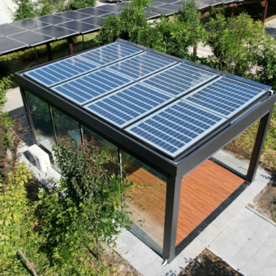
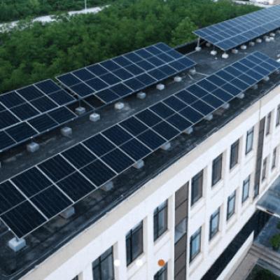
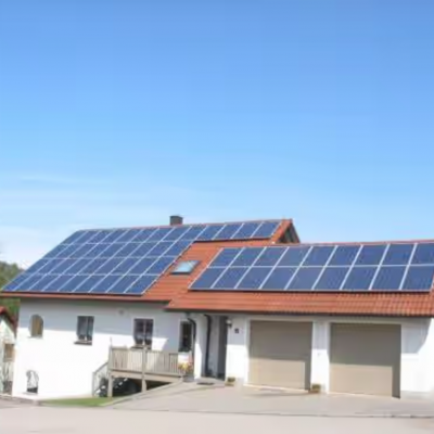
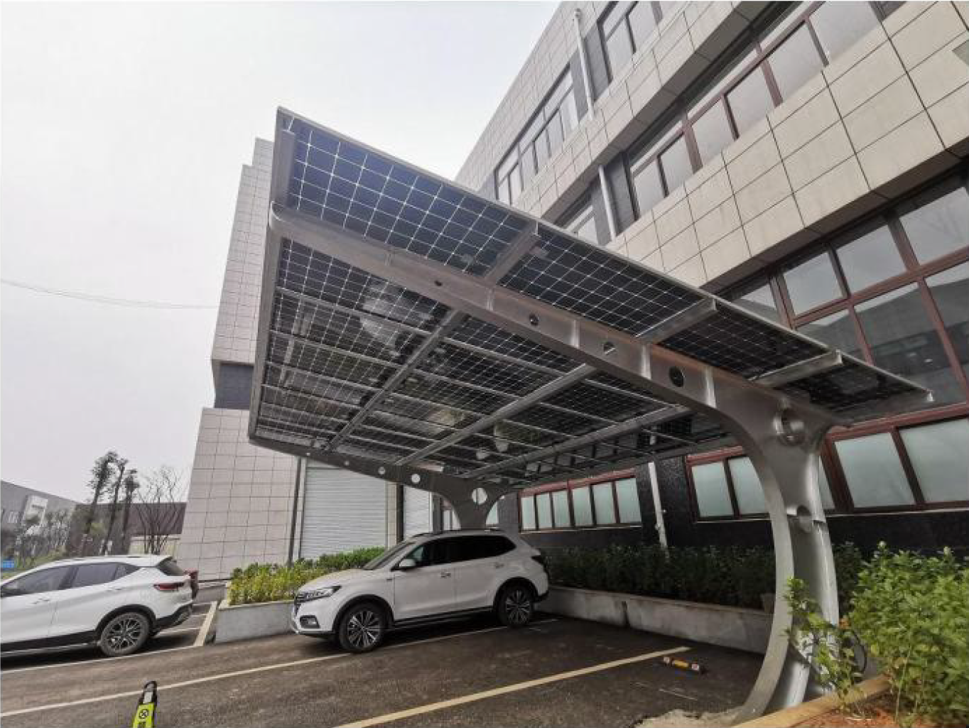
15kw charging photovoltaic carport in Nanjing
Ⅰ.Project Overview
This project is located in Nanjing, Jiangsu
Province. Nanjing is located at the intersection of China's east-west artery,
the Yangtze River, and the north-south artery, the Beijing Shanghai Railway.
With a total area of 6587 square kilometers and a population of 8.27 million,
the city's comprehensive competitiveness ranks among the top in the country. In
2020, the gross domestic product of Nanjing region was 1.481795 trillion yuan,
ranking 10th in the country, and the total economic output returned to the top
ten in the country, an increase of 4.6% over the previous year. The per capita
regional GDP is 159100, ranking third in China and first among provincial
capitals. Nanjing is an important comprehensive industrial base in China, with
electronic and chemical production capacity ranking second in the country, and
vehicle manufacturing scale ranking third. A comprehensive industrial system
has been formed, dominated by electronic information, automobiles,
petrochemicals, and a number of characteristic products, with 36 industrial
categories, over 200 categories, and more than 2000 major product categories.
The number and scale of large enterprises rank among the top in cities across
the country.
Nanjing has a humid climate in the northern subtropical region, with distinct four seasons and abundant rainfall. The average annual rainfall is 117 days, with an average rainfall of 1106.5 millimeters, a relative humidity of 76%, and a frost free period of 237 days. The rainy season is from late June to early July every year. The annual average temperature is 16.5 ° C, with the highest annual extreme temperature being 39.7 ° C and the lowest being -13.1 ° C.
Ⅱ.System scheme design
1. Overall scheme design
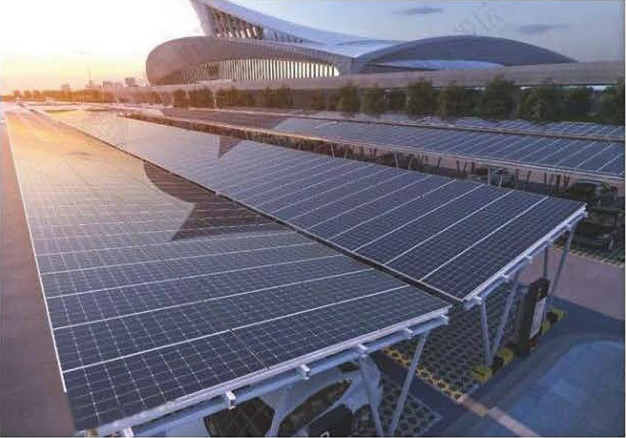
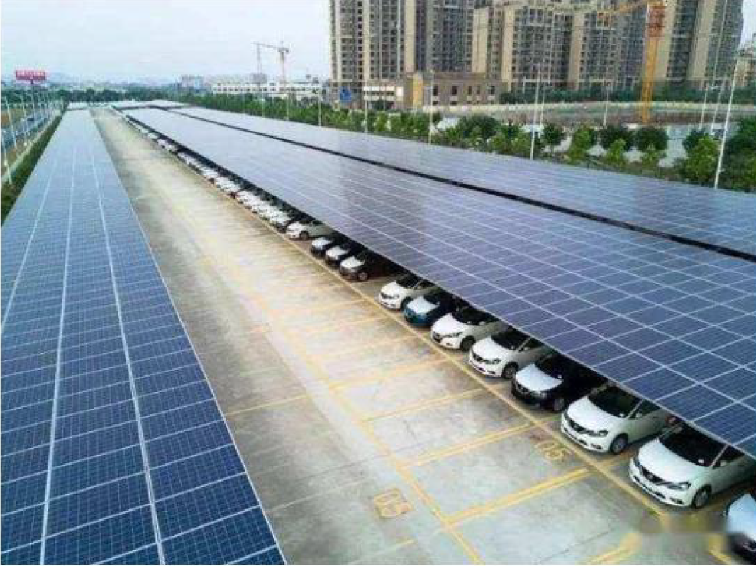
The project is a photovoltaic power station system with 6 parking spaces and parking sheds, with a total installed capacity of 15360W. It uses 320 watt high-efficiency monocrystalline solar panels, 15 kW grid connected solar inverters, and the shed support is made of galvanized steel with strong wind, earthquake, and pressure resistance performance. The grid connection point is located indoors within 100 meters.
Size of carport
5.32-meter spacing, 4 support columns per bike seat
2.66-meter width, total height of 6 parking spaces: 2 meters behind, 3 meters
in front, Q235B material, fluorocarbon paint surface treatment.
Car parking space
6 of them
Installed capacity
15360W
Photovoltaic modules
48 pieces, size 1640 * 992 * 35mm, specification 320Wp
monocrystalline photovoltaic modules.
inverter
One 15kW well grid inverter
After the construction of the photovoltaic carport, a charging pile project can be added on the basis of the photovoltaic carport project through secondary configuration. The charging pile energy storage power supply system is divided into three parts: PCS, lithium battery energy storage system, and charging pile system. The lithium battery energy storage system is composed of retired electric vehicle batteries. The project site is equipped with two PCS energy conversion systems with a power of 8kW and a capacity of 15.36kW · h lithium battery energy storage system. According to the time of use electricity price of the main peak valley, it is 0.14 USD from 8am to 12pm, 0.62 yuan from 12pm to 6pm, 1.07 yuan from 6pm to 10pm, and 0.05 USD from 10pm to 8am.
(1) Utilization of photovoltaic power
generation in carport:
During the daytime photovoltaic power
generation period, it belongs to the peak period of electricity prices or
electricity consumption. Photovoltaic power generation is directly supplied to
local loads for self use, achieving maximum photovoltaic power generation
revenue.
(2) Charging of PCS lithium battery energy
storage system:
During the low electricity price period,
the power grid charges it (from 10 pm to 8 am, 16kW PCS can fully charge the
lithium battery energy storage system with 15.36kW · h
battery capacity in 7.5 hours)
(3) Discharge of PCS lithium battery energy
storage system
During the day, the energy storage system
outputs electrical energy to charging stations, or releases electrical energy
to local loads during periods of surplus electricity or peak electricity
prices.
Summary
By utilizing the PCS lithium battery energy
storage system's bidirectional flow of electricity and peak valley time of use
electricity pricing, known as "low price storage, high price use" of
electricity, on the one hand, low-cost charging pile power supply can be
achieved, and on the other hand, local load electricity consumption can be
reduced during peak electricity pricing periods, saving electricity costs.
There are two types of charging station
systems: DC charging stations and AC charging stations.
The DC charging station directly converts
the DC power of the lithium battery energy storage system through DC-DC
conversion to obtain electrical energy output. Its characteristics include high
output power and fast charging speed for electric vehicles.
2. Selection of grid connected inverters
Grid connected inverter is the core
conversion equipment of photovoltaic grid connected power generation system. It
connects the DC side and AC side and needs to have complete protection function
and high-quality power output. The selection of inverters must meet the
following requirements:
(1) High conversion efficiency
The higher the conversion efficiency of the
inverter, the higher the conversion efficiency of the photovoltaic power
generation system, the smaller the total power generation loss of the system,
and the higher the system economy. Therefore, when the rated capacity of a
single unit is the same, a high-efficiency inverter should be selected. The
inverter conversion efficiency includes maximum efficiency and European
efficiency. European efficiency is a weighted efficiency of different power
points, which better reflects the comprehensive efficiency characteristics of
the inverter. The output power of photovoltaic power generation systems varies
continuously with the intensity of sunlight, so during the selection process,
high-efficiency inverters from Europe should be chosen.
(2) Wide range of DC input voltage
The terminal voltage of solar cell modules
varies with the intensity of sunlight and environmental temperature. The DC
input voltage range of the inverter is wide, which can utilize the power
generation during the time periods before sunrise and after sunset when the
solar irradiance is low, thereby extending the power generation time and
increasing the power generation.
(3) High quality electrical energy output
Inverters should have high-performance
filtering circuits to ensure high quality AC output power without polluting the
power grid. When the output power is greater than 50% of the rated power and
the grid fluctuation is less than 5%, the total harmonic distortion (THD) of
the inverter's AC output current is less than 3%.
During the operation of grid connected
inverters, real-time collection of voltage signals from the AC power grid is
required. Through closed-loop control, the phase of the inverter's AC output
current is kept consistent with the grid voltage, so the power factor can be
maintained around 1.0.
(4) Effective measures to protect against
the "island effect"
Multiple "islanding effect"
detection methods are adopted to ensure accurate tracking and detection of
parameters such as voltage, frequency, and phase when the power grid loses
power, timely judgment of the power supply status of the power grid, accurate
operation of the inverter, and ensuring the safety of the power grid.
(5) System frequency abnormal response
The "Technical Regulations for
Connecting Photovoltaic Power Stations to the Power Grid of State Grid
Corporation of China" require large and medium-sized photovoltaic power
stations to have a certain ability to withstand system frequency anomalies.
(6) Communication function
Photovoltaic grid connected inverters must
provide communication interfaces that can upload real-time operating data,
fault information, alarm information, etc. of the inverter to the power station
monitoring system.
Based on the actual situation on site and
the limited roof conditions in the photovoltaic module installation area, it is
recommended to use string inverters. Compared to centralized inverters, the
advantages of string inverters are as follows.
High conversion efficiency, with a European
efficiency of 97.5%;
Multi channel MPPT ultimately ensures high
system conversion efficiency;
The power generation revenue is
significantly higher than that of centralized inverters:
No need for DC convergence;
Easy installation, tailored to local
conditions, space saving;
Easy maintenance and shortened average
maintenance time;
Wide input range, longer power generation
efficiency;
Overall consideration:
3. Selection of Photovoltaic Modules
This project plans to use 535Wp
high-efficiency monocrystalline silicon battery modules. The component
parameters are shown in the following table
|
Sn. |
Parameter Name |
performance parameter |
|
1 |
Photoelectric conversion efficiency of full illuminated area (including frame area) |
20.75% |
|
2 |
peak power |
535W |
|
3 |
working voltage |
40.63V |
|
4 |
Working current |
13.17A |
|
5 |
Open circuit voltage |
49.34V |
|
6 |
short-circuit current |
13.79A |
|
7 |
External dimensions |
2274mm*1134mm*35mm |
|
8 |
working temperature |
-40℃~85℃ |
|
9 |
Service life |
25 years |
Number Parameter Name Performance
Parameters
The photoelectric conversion efficiency of
1 full illuminated area (including frame area) is 20.75%
Peak power of 535W
3. Operating voltage 40.63V
4 working current 13.17A
5. Open circuit voltage 49.34V
6 Short circuit current 13.79A
7. Dimensions: 2274mm * 1134mm * 35mm
8 Working temperature -40 ℃~85 ℃
9 lifespan of 25 years
4. Component bracket design
The bracket shall be made of Q235B
cold-rolled steel plate or aluminum profile, and the material selection and
bracket design shall comply with the provisions of the national standard
"Code for Design of Steel Structures" GB50017. The anti-corrosion of
the bracket should meet the following requirements:
The crossbeam, color steel tile fixtures,
and crossbeam connectors are all processed first and then hot-dip galvanized.
The zinc layer should comply with GB/T13912-2002, and the thickness of the zinc
layer should not be less than 65um. The aluminum alloy surface should be
anodized with primary color AA15.
All bolts in this project shall comply with
the current national standard "Hexagonal Bolt-C Grade" (GB5780) and
have on-site anti-corrosion requirements.
The edge pressure block and middle pressure
block are made of aluminum alloy material;
According to the Code for Seismic Design of
Buildings (GB50011-2010), the seismic intensity of the support system is 7
degrees, the seismic peak acceleration in the engineering area is 0.1g, and the
characteristic period of the seismic response spectrum is 0.40S
The fixed bracket should be made of
corrosion-resistant steel profiles, and all connection points (welding points)
should be reliably connected to avoid looseness. It is required to be able to
withstand outdoor corrosion such as wind, frost, rain, and snow.
The fixed bracket can meet the requirements
of installation inclination, wind resistance, snow pressure resistance, seismic
resistance, corrosion resistance, safety, universality, and quick installation.
Tilt angle design
5. Cable selection
(1) Selection principle
Environmental condition verification
ambient temperature
sunshine
wind speed
Filth
Altitude
The selection and laying design of wires
and cables for photovoltaic power plants should comply with the provisions of
the "Code for Design of Cables in Power Engineering" GB50217, and the
cross-section of wires and cables should be selected and determined after
technical and economic comparison.
Cables that are centrally laid in channels
and troughs should use Class C or above flame-retardant cables.
The wires and cables between photovoltaic
modules and between modules and combiner boxes should have fixed measures and
sun protection measures.
Cable laying can be done through direct
burial, cable trenches, cable trays, cable trunking, and other methods. Power
cables and control cables should be arranged separately and meet the minimum
spacing requirements
Cable trenches are strictly prohibited from
being used as drainage channels.
Fiber optic cables should be used as
network cables for long-distance transmission,
Selection of rated voltage for cables
The rated voltage between phases of power
cable cores in the communication system shall not be lower than the working
line voltage of the circuit in use.
The selection of rated voltage between
power cables and insulation shields or metal sleeves in communication systems
shall comply with the following regulations:
① When the grounding protection action of a
system with a neutral point directly grounded or grounded through low impedance
does not exceed 1 minute to cut off the fault, the operating phase voltage of
the circuit should be 100%.
② For power supply systems outside of item
a, the operating phase voltage of the circuit should not be lower than 133%; In
situations where a single-phase grounding fault may last for more than 8 hours,
or where safety requirements are high for generator circuits, it is advisable
to use 173% of the operating phase voltage of the circuit.
2) The impact withstand voltage level of
cables in the communication system should meet the insulation coordination
requirements of the system.
3) The insulation level of DC transmission
cables should take into account load variation factors and meet the
requirements of internal overvoltage.
4) The selection of rated voltage for
control cables should not be lower than the working voltage of the circuit and
meet the requirements of transient and power frequency overvoltage that may be
experienced. And declare that it complies with the following regulations
① Control cables (guide cables) laid in
parallel along longer high-voltage cables shall be selected with appropriate
rated voltage.
② For control cables laid in high voltage
distribution equipment of 220kV and above, 600/1000V should be selected, or
450/750V can be selected when there is good shielding.
③ Except for situations ① and ②, it is generally recommended to use
450/750V; When external electrical interference is minimal, a lower rated
voltage can be used.
Selection of cable cross-sectional area;
The cable cross-section should meet the
requirements of continuous allowable current, short-circuit thermal stability,
allowable voltage loss, etc. For long-distance high current circuits, it is
also advisable to choose according to the economic current density.
(2) Cable model
According to the selection criteria, the
cable models and specifications selected for this project are as follows:
1) PV1-F1x4mm2 cable is selected for the
output from the photovoltaic array string to the inverter;
2) The output cable of the 20KW inverter is
selected as ZC-YJV-0.6/1kV-4 * 16 mm2
6. Energy storage system and PCS design
As a power conversion device between the
power grid and the battery in the energy storage system, energy storage devices
can achieve bidirectional energy exchange between the power grid and the
battery pack. They are used for "peak shaving and valley filling" of
the power grid, regulating the continuity and stability of renewable energy
generation systems, and serving as emergency and backup power sources for
important departments and facilities. This device can be used in new energy
power stations, electric vehicle charging and swapping stations, urban energy
storage stations, and microgrid energy storage, and has good application
prospects.
Performance characteristics:
High safety performance: using a power
frequency transformer to safely isolate the battery from the power grid
High conversion efficiency: using
first-order transformation, simple structure, easy control, energy conversion
effect
Multiple operating modes: constant current
charging and discharging, constant power charging and discharging, float
charging, constant voltage charging, and other multiple modes
Rich communication interfaces: equipped
with multiple communication interfaces such as CAN2.0, RS485, LAN, etc.,
facilitating the implementation of various communication methods
Advanced control technologies:
internationally leading control and protection technologies such as soft
phase-locked loop, voltage feedforward, vector control, etc
Complete protection functions: module
level, device level, and system level three-layer protection
7. Lightning protection and grounding
The lightning protection and grounding of the steel structure carport photovoltaic project and solar photovoltaic power station in this project are mainly based on GB50057-94 "Code for Design of Lightning Protection of Buildings"
The lightning intrusion path of photovoltaic power generation systems includes not only photovoltaic modules, but also distribution lines, grounding wires, and their combinations. In order to ensure the safe operation of the power system and the safety of photovoltaic power generation and power facilities, grid connected photovoltaic power stations must have good lightning protection, lightning protection, and grounding protection devices.
Due to the fact that the installation location of outdoor equipment in this project is not the tallest building in the entire environment, all steel structures are connected and connected to the newly added grounding piles to form a lightning protection network, in order to achieve the purpose of lightning protection.
This project adopts the following lightning protection and grounding measures
The aluminum alloy frame and metal bracket of the component are reliably welded to the lightning protection flat steel strip through grounding flat steel. Reliable grounding is crucial for system lightning protection and safe electricity usage. In this design, the brackets, photovoltaic module frames, and connectors are all metal products. The photovoltaic array naturally forms an equipotential body and is reliably connected to the nearest grounding grid. The grounding resistance of each connection point should be less than 4 ohms. The AC output of the inverter is connected to the power grid through an AC combiner box (containing lightning protection devices), which can effectively prevent equipment damage caused by lightning strikes and power grid surges. All cabinets must have good grounding, and the grounding resistance of each connection point should be less than 4 ohms.
Ⅲ.Analysis of power generation and benefits
1. Theoretical power generation
The monthly and annual peak sunshine hours of this project can be obtained based on the average total solar radiation in each month of the project location. Peak sunshine hours: The amount of solar radiation that can be received on the plane where the solar cell module is located during a certain period of time is converted into equivalent hours under standard operating conditions with an irradiation intensity of 1000W/m2, which is called peak sunshine hours.
If the solar radiation received by the solar cell module in 1 hour is 1kWh/m2. a, defined by the peak sunshine hours above, the peak sunshine hours t can be obtained:
t=(1kWh/m2.a)/(1000W/m2)=1(h/a)
Since the peak power of solar cell modules is calibrated under the condition of 1000W/m2, the maximum theoretical power generation of the photovoltaic power station is calculated by multiplying the peak sunshine hours by the installed capacity of the photovoltaic power station.
In this plan, a total of 48 monocrystalline silicon photovoltaic modules with a standard capacity of 320Wp will be installed, with a total installed capacity of 15.36KWp. The size of the selected photovoltaic module is 1640mm * 992mm * 35mm, and the installation method is fixed and tilted on the bracket.
The annual effective light exposure time in Huanggang area is 1913.5-2161.5 hours. After calculation, the theoretical annual power generation of the photovoltaic array in this project is 29391.36 kWh.
2. Theoretical annual power generation
The theoretical power generation of a photovoltaic power station in the first year is the maximum theoretical power generation of the photovoltaic power station multiplied by the attenuation coefficient of the solar cell module in the first year. The attenuation coefficient of the monocrystalline silicon solar cell modules selected for this project in the first year is 8%, so the theoretical power generation of the photovoltaic power station in the first year is the annual theoretical power generation multiplied by the module reduction coefficient.
3. Efficiency analysis of photovoltaic power generation system
The efficiency of solar photovoltaic power generation system includes: solar cell aging efficiency, AC/DC low-voltage system loss and other equipment aging efficiency, inverter efficiency, transformer and grid loss efficiency; Based on the actual power generation situation and empirical coefficients of relevant projects at home and abroad, the values of each efficiency coefficient are as follows:
(1) DC cable loss: 2%;
(2) Anti reverse diode and cable connector loss: 1.5%;
(3) Loss caused by mismatched battery panels: 4%;
(4) Dust blocking loss: 2%;
(5) AC line loss: 0.8%;
(6) Inverter loss: 2%;
(7) Unusable solar radiation loss: 1.2%;
(8) System failures and maintenance losses: 1%;
(9) Transformer loss: 3%;
(10) Temperature effect loss: 4%;
After calculation and analysis, the overall efficiency of the system is 81%.
Ⅳ.Economic and social benefits
1. Economic benefits
Based on the above analysis, the total installed capacity of the photovoltaic power station in this project is 15.36kWp, and the cumulative power generation during 25 years of continuous operation is 595175kW · h.
Photovoltaic power generation saves electricity costs: Due to the relatively small installed capacity of photovoltaics compared to the power load, most of the energy generated by photovoltaics can be used for self use. With a design life of 25 years for photovoltaic power stations, based on an electricity price of 0.8 yuan, it is estimated that electricity costs will be saved by 476140 yuan;
2. Comprehensive environmental benefits
Photovoltaic power generation has no pollution to the environment and no greenhouse gas emissions during the power generation process, which is a huge advantage of solar photovoltaic power generation. At present, the main power supply in China still comes from coal-fired power generation. During the process of coal combustion, a large amount of harmful gases such as sulfur dioxide are emitted, which pollutes the environment and emits a large amount of carbon dioxide. As is well known, carbon dioxide is a greenhouse gas, and its excessive emissions are an important factor in global warming. After the operation of the photovoltaic power generation system, it has completely zero emissions. Based on the stable operation of the photovoltaic power generation system for 25 years, the theoretical cumulative power generation of this photovoltaic power generation system can reach 595175kW-h.
Note: For every 1 kWh of electricity saved, 0.36 kg of standard coal is saved, while reducing pollution emissions by 0.272 dry grams of carbon dust and 0.997 dry grams of carbon dioxide (0.03 dry grams of CO2) and 0.015 dry grams of ammonia oxide (NOx).
